

Maintaining signal integrity is a critical aspect of developing reliable and high-performance electronic products. As devices become faster and more complex, ensuring that signals travel through circuits without distortion, interference, or loss is essential for proper operation. Whether you’re designing consumer electronics, industrial controls, or communication systems, understanding how to manage signal quality can make the difference between a robust product and one plagued by unpredictable failures.
This article explores the fundamentals of signal quality, common challenges faced during development, and practical strategies for engineers and designers. We’ll also highlight best practices and provide resources for further reading, including a helpful electronic product design system integration guide that covers broader integration topics relevant to signal management.
Understanding Signal Integrity in Modern Circuit Design
At its core, signal integrity in electronic product design refers to the preservation of signal quality as electrical pulses travel through a printed circuit board (PCB) or other interconnects. Poor signal integrity can result in data errors, timing issues, electromagnetic interference (EMI), and even complete system failures. As clock speeds and data rates increase, even minor design oversights can have significant impacts.
Key factors influencing signal quality include:
- Impedance mismatches that cause signal reflections
- Cross-talk between adjacent traces or components
- Power supply noise and ground bounce
- PCB layout and routing choices
- Component selection and placement
Addressing these factors early in the design process is essential for ensuring reliable operation, especially in high-speed or sensitive applications.
Common Signal Integrity Issues in Electronic Products
Several challenges can compromise the quality of signals in electronic assemblies. Recognizing these issues is the first step toward effective mitigation:
- Reflections: Occur when signals encounter impedance changes, causing part of the signal to bounce back toward the source. This can distort the original waveform and lead to data corruption.
- Cross-talk: Unintended coupling between adjacent traces or cables can induce noise, especially in densely packed PCBs.
- Ground bounce: Rapid switching of digital circuits can cause voltage fluctuations in the ground plane, affecting reference levels and signal thresholds.
- Electromagnetic interference (EMI): External or internal sources of EMI can disrupt signal transmission, particularly in environments with many wireless devices or motors.
- Signal attenuation: Over long traces or cables, signals can lose strength, making them more susceptible to noise.
Each of these problems can be addressed through careful design, simulation, and validation, ensuring that products meet performance and regulatory requirements.
Best Practices for Enhancing Signal Quality
To achieve robust signal integrity in your projects, consider the following practical strategies:
- Controlled impedance routing: Match trace impedance to source and load to minimize reflections. Use impedance calculators and PCB stackup planning tools.
- Short, direct signal paths: Keep high-speed or sensitive traces as short and direct as possible to reduce the risk of cross-talk and attenuation.
- Proper layer stackup: Arrange PCB layers to provide solid reference planes for signals, reducing EMI and ground bounce.
- Differential signaling: Use differential pairs for high-speed data lines to improve noise immunity and reduce EMI.
- Decoupling capacitors: Place capacitors close to power pins of ICs to filter out noise and stabilize supply voltages.
- Simulation and modeling: Use signal integrity simulation tools to predict and address issues before fabrication.
By integrating these practices into your workflow, you can significantly reduce the risk of signal-related failures and improve overall product reliability.
Design Considerations for High-Speed and Sensitive Circuits
As data rates increase, maintaining signal integrity in electronic product design becomes more challenging. Here are some additional considerations for high-speed and sensitive applications:
- Minimize stubs: Avoid unnecessary branches or stubs on signal traces, as these can act as antennas and introduce reflections.
- Matched trace lengths: For differential pairs or parallel data buses, ensure traces are matched in length to prevent skew and timing errors.
- Shielding: Use ground fills, guard traces, or metal enclosures to shield sensitive signals from external EMI sources.
- Controlled rise and fall times: Avoid excessively fast signal transitions, which can generate unwanted harmonics and EMI.
- Careful connector selection: Choose connectors rated for the required frequency and impedance to prevent signal degradation at interfaces.
These techniques are especially important in applications such as USB, HDMI, Ethernet, and RF circuits, where even small signal distortions can lead to data loss or communication failures.
Testing and Validation of Signal Integrity
Verification is a crucial step in ensuring that your design meets signal quality requirements. Common validation approaches include:
- Time-domain reflectometry (TDR): Measures impedance along traces to identify mismatches and discontinuities.
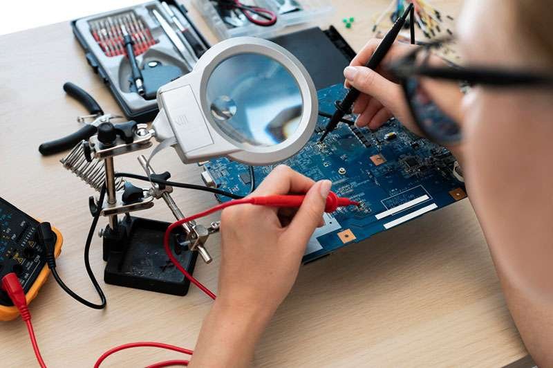
- Oscilloscope measurements: Capture waveforms to check for ringing, overshoot, and timing errors.
- Eye diagram analysis: Visualizes the quality of digital signals, revealing jitter, noise, and other impairments.
- EMI/EMC testing: Ensures that the product meets regulatory standards for electromagnetic compatibility.
Incorporating these tests into your workflow helps catch issues early, reducing costly redesigns and improving time to market. For a deeper dive into performance validation, the electronic product design performance testing guide offers additional insights.
Cost Implications and Industry Resources
Addressing signal quality concerns early in the development process can save significant costs by avoiding late-stage redesigns and compliance failures. Investing in simulation tools, training, and robust design practices pays off in the form of fewer field failures and improved customer satisfaction. For those interested in budgeting and planning, this overview of electronic product design service costs provides a useful perspective on industry pricing and considerations.
Staying up to date with industry standards and best practices is also essential. Many organizations publish guidelines and reference materials to help engineers navigate the complexities of signal management in modern products.
Integrating Signal Integrity with Broader Design Workflows
Signal quality is just one aspect of a successful product development process. It must be considered alongside documentation, safety, reliability, and system integration. Coordinating these disciplines helps ensure that all requirements are met and that the final product performs as intended. For more information on documentation and reliability, see the electronic product design documentation workflow and electronic product design reliability engineering basics.
By adopting a holistic approach, teams can better manage trade-offs and deliver products that excel in performance, compliance, and user satisfaction.
Frequently Asked Questions
What is signal integrity and why is it important in electronic product development?
Signal integrity refers to the ability of an electrical signal to propagate through a circuit without significant degradation or distortion. It is crucial because poor signal quality can lead to data errors, communication failures, and reduced product reliability, especially in high-speed or sensitive applications.
How can I improve signal integrity in my PCB designs?
Improving signal quality involves several strategies, such as matching trace impedance, minimizing trace lengths, using proper PCB stackups, placing decoupling capacitors near ICs, and leveraging simulation tools to predict and address issues before manufacturing.
What tools are available for testing signal integrity?
Common tools include oscilloscopes for waveform analysis, time-domain reflectometers (TDR) for impedance measurements, and eye diagram analyzers for digital signal assessment. EMI/EMC testing equipment is also used to ensure compliance with regulatory standards.