

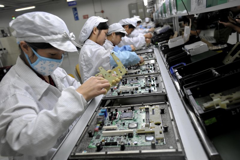
Ensuring the integrity of printed circuit boards (PCBs) is a critical step in electronics manufacturing and maintenance. A reliable PCB forms the backbone of any electronic device, and even minor defects can lead to malfunction, reduced performance, or complete failure. Understanding the right procedures and tools for evaluating PCB quality helps prevent costly issues down the line and supports long-term product reliability.
This article provides a comprehensive overview of the most effective methods and best practices for verifying the condition and performance of your circuit boards. Whether you are an engineer, technician, or electronics hobbyist, learning how to assess PCB health will help you maintain high standards in your projects and products.
For those interested in a broader perspective on electronics testing, the electronic product design performance testing guide offers additional insights into comprehensive product evaluation.
Why PCB Condition Matters
The durability and functionality of a PCB directly impact the performance of the entire electronic system. Common issues such as broken traces, cold solder joints, or delamination can cause intermittent faults that are difficult to diagnose. Regular inspection and testing help catch these problems early, reducing the risk of field failures and warranty claims.
Manufacturers and designers must prioritize thorough verification processes to ensure that every board meets quality standards before assembly and deployment. This focus on quality control not only improves customer satisfaction but also enhances the reputation of the brand.
Visual Inspection: The First Step in PCB Evaluation
One of the most accessible and cost-effective methods for assessing board quality is visual inspection. This process involves carefully examining the board for visible defects, such as:
- Cracks or breaks in traces and pads
- Misaligned or missing components
- Cold or cracked solder joints
- Signs of corrosion or contamination
- Delamination or warping of the board substrate
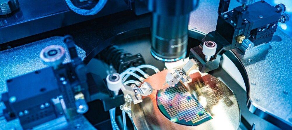
Using magnification tools, such as a microscope or a magnifying lamp, can help identify subtle issues that are not visible to the naked eye. Automated optical inspection (AOI) systems are also widely used in manufacturing environments to speed up and standardize this process.
Electrical Testing Methods for Assessing Board Health
After visual checks, electrical testing provides a more in-depth look at the board’s functionality. Several techniques are commonly used to verify electrical performance and pinpoint faults:
Continuity and Isolation Testing
Continuity testing ensures that all intended connections on the board are present and unbroken. Using a multimeter or dedicated test equipment, you can check that signals flow correctly between pads and components. Isolation testing, on the other hand, verifies that there are no unintended connections (shorts) between traces that should be isolated.
In-Circuit Testing (ICT)
ICT is a popular automated method for checking assembled boards. It uses a bed-of-nails fixture or flying probes to make contact with test points on the PCB, measuring resistance, capacitance, and other parameters to confirm correct assembly and detect faults.
Functional Testing
This approach involves powering up the board and running it through its intended functions to ensure all circuits operate as designed. Functional tests can be manual or automated, depending on the complexity of the product.
Advanced Techniques for Ensuring PCB Reliability
For high-reliability applications, additional testing methods may be necessary. These include:
- X-ray inspection for detecting hidden solder joint defects, especially under components like BGAs (Ball Grid Arrays)
- Thermal imaging to identify hotspots or areas of excessive power dissipation
- Flying probe testing for low- to medium-volume production, offering flexibility without the need for custom fixtures
- Environmental stress screening to simulate real-world operating conditions and uncover latent defects
For a deeper dive into modern electronic component verification, the article on electronic component testing standard and advanced techniques provides a detailed overview of industry practices.
Common Issues Detected During PCB Evaluation
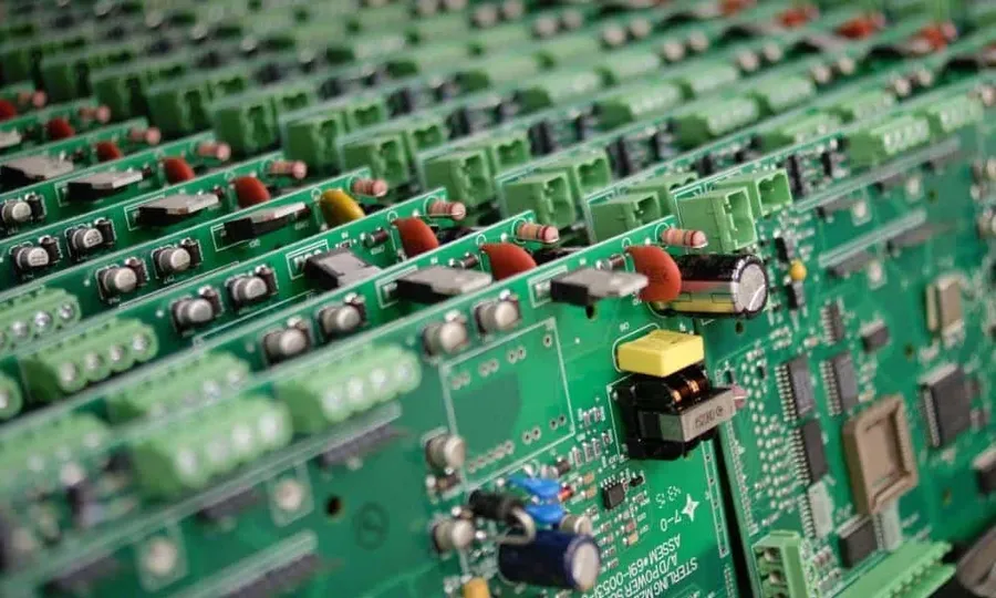
Routine checks often reveal a range of problems that can compromise circuit board performance. Some of the most frequent issues include:
- Open circuits due to broken traces or poor soldering
- Short circuits caused by solder bridges or conductive debris
- Component misplacement or incorrect orientation
- Delamination or blistering of the board material
- Corrosion from environmental exposure
Addressing these concerns early in the production or repair process helps avoid downstream failures and supports a robust quality assurance program.
Best Practices for Maintaining PCB Quality
To ensure lasting reliability, it’s essential to integrate regular inspection and testing into your workflow. Some best practices include:
- Establishing clear inspection criteria and checklists
- Training staff on proper handling and evaluation techniques
- Using appropriate tools and equipment for each stage of testing
- Documenting all findings and corrective actions
- Implementing feedback loops to improve design and manufacturing processes
Material selection also plays a significant role in overall board durability. For more information on choosing the right materials, refer to the electronic product design pcb material selection guide.
Frequently Asked Questions
What tools are essential for checking the condition of a PCB?
Basic tools include a multimeter for electrical continuity and isolation tests, magnifying lamps or microscopes for visual inspection, and soldering equipment for repairs. In manufacturing, automated optical inspection and in-circuit testers are commonly used.
How often should PCBs be tested during production?
Boards should be inspected at multiple stages: after fabrication, post-assembly, and before final product integration. Regular spot checks and batch testing help maintain consistent quality and catch issues early.
Can environmental factors affect PCB reliability?
Yes, exposure to moisture, extreme temperatures, and corrosive environments can degrade board materials and solder joints. Environmental stress screening and protective coatings are recommended for products used in harsh conditions.
Conclusion
Verifying the health of your circuit boards is a crucial part of electronics manufacturing and maintenance. By combining visual inspection, electrical testing, and advanced diagnostic techniques, you can ensure that your products meet high standards for reliability and performance. Integrating these methods into your workflow not only reduces the risk of failure but also supports continuous improvement in your design and production processes.
