

Printed circuit boards (PCBs) are the heart of modern electronics, but even the most carefully designed boards can encounter issues during development or production. Understanding how to debug a PCB is essential for engineers, technicians, and hobbyists who want to ensure reliable performance and minimize costly delays. This guide covers proven methods, essential tools, and practical steps for identifying and resolving faults in circuit boards, whether you’re working on prototypes or troubleshooting production units.
Before diving into the debugging process, it’s helpful to be familiar with the fundamentals of PCB design and testing. For those interested in a broader perspective on product validation, the electronic product design performance testing guide offers a comprehensive overview.

Understanding Common PCB Issues
Before starting any troubleshooting, it’s important to recognize the types of problems that typically occur in circuit boards. These can range from simple soldering defects to complex signal integrity issues. Some of the most frequent challenges include:
- Open circuits caused by broken traces or poor solder joints
- Short circuits due to solder bridges or misplaced components
- Component failures such as damaged ICs, resistors, or capacitors
- Incorrect component placement or orientation
- Power supply issues including voltage drops or noise
- Signal integrity problems like crosstalk or reflections
Recognizing these symptoms early can help you focus your debugging efforts and select the right tools for the job.

Essential Tools for Effective PCB Troubleshooting
Having the right equipment is crucial for diagnosing and fixing faults efficiently. Here are some of the most commonly used tools when working through the process of how to debug a PCB:
- Multimeter: For measuring voltage, current, resistance, and continuity.
- Oscilloscope: To visualize signal waveforms and detect anomalies.
- Logic analyzer: Useful for digital circuits to monitor multiple signals simultaneously.
- Soldering iron and rework station: For repairing solder joints or replacing components.
- Magnifying glass or microscope: To inspect for tiny solder bridges or cracks.
- Power supply: Provides controlled voltage and current for safe testing.
- Test probes and clips: For making secure connections to test points.
Depending on the complexity of the board, more advanced tools like thermal cameras or in-circuit testers might also be beneficial.
Step-by-Step Approach to Diagnosing PCB Faults
A systematic approach is the most efficient way to uncover and resolve issues. Below is a practical sequence for debugging circuit boards:
- Visual Inspection: Start by carefully examining the board for obvious defects. Look for burnt components, cracked solder joints, missing parts, or foreign objects. A microscope can reveal issues invisible to the naked eye.
- Check Power Rails: Use a multimeter to verify that all power supply voltages are correct and stable. Unexpected readings can indicate shorts, open circuits, or faulty regulators.
- Continuity Testing: Test for open or short circuits between traces and pads. This can quickly identify broken connections or unintended bridges.
- Component Verification: Confirm that all parts are correctly placed and oriented. Double-check values against the bill of materials and schematic.
- Signal Analysis: Use an oscilloscope or logic analyzer to probe critical signals. Look for missing, distorted, or unexpected waveforms.
- Functional Testing: If the board powers up, run basic functional tests to see which sections are working and which are not. Isolate the problem area for further investigation.
- Targeted Rework: Once a fault is identified, repair the issue—resolder joints, replace components, or correct wiring as needed. Retest after each fix.
Documenting each step and result can help avoid redundant work and provide valuable insights for future projects.
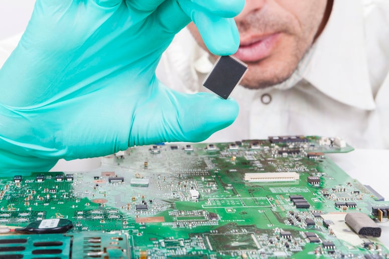
Advanced Techniques for Complex PCB Debugging
Some faults are not immediately obvious and require more sophisticated methods. For multilayer boards or high-speed designs, consider these approaches:
- Thermal Imaging: Use an infrared camera to detect overheating components, which may indicate excessive current draw or short circuits.
- Boundary Scan (JTAG): For digital boards, boundary scan tools can test interconnections without physical probing.
- Signal Integrity Analysis: Specialized software and oscilloscopes can help diagnose issues like reflections, crosstalk, or impedance mismatches.
- Automated Test Equipment (ATE): In production, automated systems can rapidly identify defective units and pinpoint failure modes.
For more details on the broader electronics manufacturing process and how debugging fits within it, see this in-depth guide to electronics manufacturing processes.
Best Practices to Prevent PCB Issues
While knowing how to debug a PCB is crucial, preventing faults in the first place saves time and resources. Here are some tips to minimize errors:
- Design for Manufacturability (DFM): Follow layout guidelines and checklists to reduce the risk of assembly errors.
- Use quality components: Sourcing from reputable suppliers reduces the chance of early failures.
- Perform design reviews: Peer reviews and simulations can catch mistakes before fabrication.
- Implement thorough testing: Develop test plans that cover all critical functions and edge cases.
- Maintain clear documentation: Accurate schematics, layout files, and test procedures streamline debugging and future modifications.
For those interested in optimizing material choices for reliability and performance, the electronic product design pcb material selection guide provides valuable insights.
Frequently Asked Questions
What is the first step when troubleshooting a faulty PCB?
The initial step is always a thorough visual inspection. Look for visible defects such as burnt components, poor solder joints, or misplaced parts. This can quickly reveal many common issues without the need for advanced tools.
Which tools are essential for debugging circuit boards?
At a minimum, a multimeter and oscilloscope are indispensable for most debugging tasks. Depending on the complexity of the board, you may also need a logic analyzer, soldering tools, magnification devices, and a reliable power supply.
How can I prevent recurring PCB faults in future designs?
Focus on robust design practices, including thorough reviews, using high-quality components, and implementing comprehensive testing protocols. Good documentation and clear assembly instructions also help minimize errors during manufacturing and assembly.
