

Flexible circuits—often called flex PCBs—are essential components in today’s compact, high-performance electronics. Their ability to bend, twist, and conform to tight spaces makes them ideal for everything from medical devices to consumer gadgets and automotive systems. Understanding how flex circuits are made is key for engineers, designers, and anyone interested in electronics manufacturing. This article provides a detailed, step-by-step look at the fabrication process, materials, and quality controls that define modern flexible circuit production.
For a broader perspective on integrating flexible circuits into complex assemblies, you may also find the electronic product design system integration guide helpful. This resource covers how different electronic components, including flex circuits, work together in sophisticated products.
What Are Flexible Circuits?
Flexible circuits are thin, lightweight electronic interconnects made from flexible polymer substrates. Unlike rigid printed circuit boards, these circuits can bend and flex, enabling new possibilities in product design. They are commonly used in applications where space, weight, and durability are critical, such as wearable technology, cameras, and aerospace equipment.
Their construction typically involves a combination of conductive copper traces and insulating polyimide or polyester films. This unique structure allows for both electrical connectivity and mechanical flexibility, making them indispensable in modern electronics.
Key Materials Used in Flex PCB Manufacturing
The process of fabricating flexible circuits begins with the careful selection of materials. The main components include:
- Base Substrate: Polyimide is the most widely used material due to its excellent thermal and chemical stability. Polyester is also used for less demanding applications.
- Conductive Layer: Copper foil is laminated onto the substrate to form the circuit’s conductive pathways.
- Adhesives: Specialized adhesives bond the copper to the base film and may also be used in multilayer constructions.
- Coverlay or Solder Mask: A protective layer shields the copper traces from environmental damage and electrical shorts.
Material quality directly impacts the reliability and performance of the finished circuit, so manufacturers pay close attention to sourcing and handling at every stage.
Step-by-Step Process: Manufacturing Flexible Circuits
The journey from raw materials to finished flexible circuits involves several precise steps. Here’s a breakdown of the typical process:
1. Substrate Preparation
The process starts with cleaning and preparing the flexible base material. Polyimide or polyester films are cut to size and cleaned to remove dust, oils, or other contaminants that could affect adhesion or circuit quality.
2. Copper Lamination
A thin sheet of copper foil is laminated onto the substrate using heat and pressure. In some cases, adhesives are used to enhance the bond. The thickness of the copper layer is chosen based on the circuit’s current-carrying requirements and flexibility needs.
3. Circuit Patterning (Imaging and Etching)
Next, the desired circuit pattern is transferred onto the copper layer. This is typically done using a photoresist process:
- A light-sensitive photoresist is applied to the copper surface.
- The circuit design is projected onto the photoresist using ultraviolet light.
- Exposed areas are developed, leaving behind the circuit pattern.
- Chemical etching removes unwanted copper, revealing the final conductive traces.
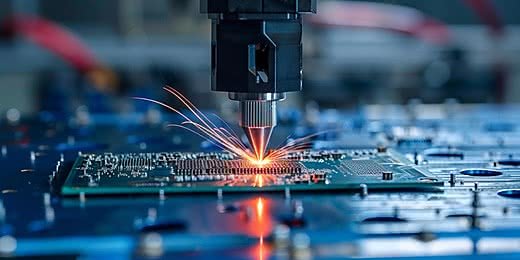
4. Drilling and Plating
If the design requires vias (holes that connect different layers or sides), these are drilled using lasers or mechanical drills. The holes are then plated with copper to ensure electrical continuity.
5. Coverlay Application
A coverlay film or liquid solder mask is applied over the circuit to protect the copper traces. Openings are created at component pads and connectors to allow for soldering and electrical contact.
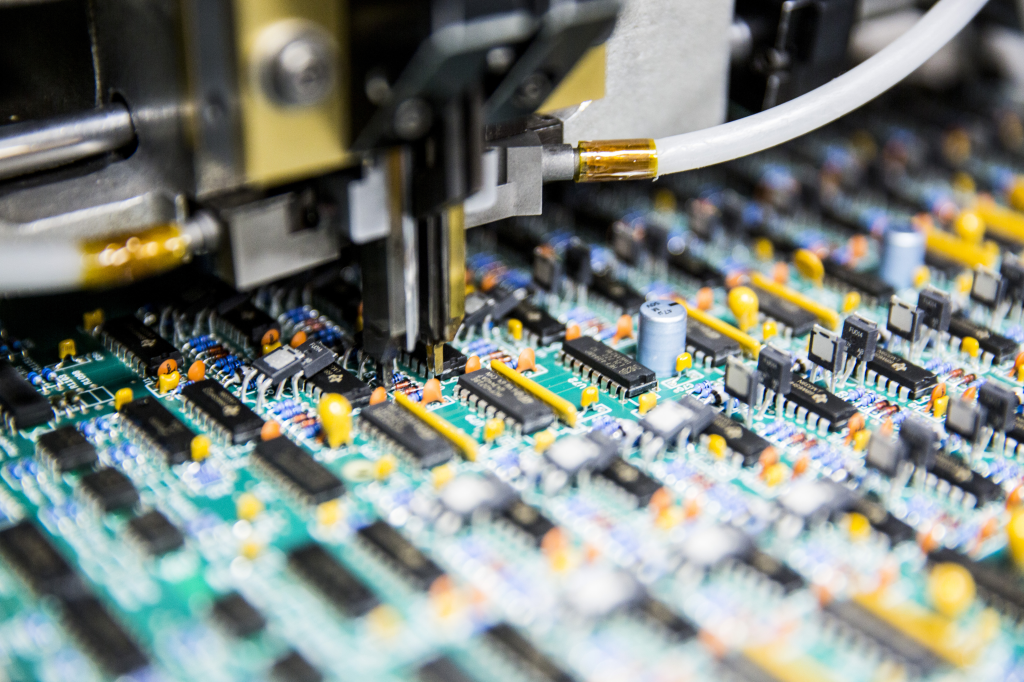
6. Component Attachment and Final Assembly
Components such as connectors, chips, or passive elements are mounted onto the flexible circuit using surface-mount or through-hole techniques. The assembly is then inspected for alignment, solder quality, and electrical performance.
Types of Flexible Circuit Constructions
There are several variations in flexible circuit design, each suited to different applications:
- Single-Sided Flex: Features copper traces on one side of the substrate. Used for simple interconnects.
- Double-Sided Flex: Copper layers on both sides, connected by plated vias. Allows for more complex routing.
- Multilayer Flex: Multiple layers of copper and polyimide stacked together. Used in advanced electronics where high-density interconnects are needed.
- Rigid-Flex: Combines rigid and flexible sections in a single assembly, providing both stability and flexibility where required.
The choice of construction depends on the mechanical, electrical, and environmental requirements of the end product.
Quality Control and Testing in Flex Circuit Production
Ensuring the reliability of flexible circuits is critical, especially for mission-critical applications. Manufacturers implement rigorous quality control measures throughout the process:
- Visual Inspection: Checks for defects such as scratches, misalignments, or incomplete etching.
- Electrical Testing: Verifies continuity and checks for shorts or open circuits.
- Mechanical Testing: Flexural and bend tests simulate real-world stresses to ensure durability.
- Environmental Testing: Exposes circuits to heat, humidity, and chemicals to confirm resistance to harsh conditions.
For a deeper dive into the broader electronics manufacturing landscape, the ultimate guide to electronics manufacturing offers valuable insights into processes, standards, and best practices across the industry.
Advantages and Challenges of Flexible PCBs
Flexible circuits offer several distinct benefits:
- Space and Weight Savings: Their thin profile and ability to bend enable more compact designs.
- Improved Reliability: Fewer connectors and solder joints reduce failure points.
- Design Versatility: They can be shaped to fit unconventional spaces or dynamic applications.
However, there are also challenges to consider:
- Complex Manufacturing: The process requires specialized equipment and expertise.
- Material Costs: High-quality polyimide and copper can be more expensive than standard PCB materials.
- Assembly Handling: Flex circuits are more delicate and require careful handling during assembly.
Applications of Flexible Circuits in Modern Electronics
The unique properties of flexible circuits have led to widespread adoption in various industries:
- Consumer Electronics: Smartphones, tablets, and wearable devices rely on flex PCBs for compact, lightweight designs.
- Medical Devices: Used in diagnostic equipment, implantable devices, and patient monitoring systems.
- Automotive: Enable advanced driver-assistance systems, lighting, and infotainment modules.
- Aerospace and Defense: Provide reliable connections in satellites, avionics, and ruggedized equipment.
For those interested in documentation and compliance aspects, the electronic product design documentation workflow guide is a useful reference for managing the technical paperwork associated with flex circuit projects.
Frequently Asked Questions
What is the main difference between flexible and rigid PCBs?
Flexible circuits use bendable polymer substrates, allowing them to flex and fit into tight spaces, while rigid PCBs are made from solid fiberglass and remain inflexible. This flexibility enables innovative product designs and reduces the need for bulky connectors.
How are multilayer flexible circuits constructed?
Multilayer flex circuits are built by stacking alternating layers of copper and polyimide, with adhesive layers in between. Vias are drilled and plated to connect the different copper layers, and the entire stack is laminated under heat and pressure to form a unified, flexible assembly.
What quality standards apply to flexible circuit manufacturing?
Most manufacturers follow IPC standards, such as IPC-6013 for flexible printed boards. These standards define requirements for materials, workmanship, and testing to ensure product reliability and performance.