

Understanding the difference between SMT and through hole assembly is essential for anyone involved in electronics manufacturing, design, or prototyping. These two assembly methods represent distinct approaches to mounting electronic components on printed circuit boards (PCBs), each with its own advantages, challenges, and ideal use cases. Whether you are a hobbyist, engineer, or decision-maker in electronics production, knowing how these techniques compare will help you make informed choices for your projects.
Before diving into the technical distinctions, it’s helpful to have a basic grasp of how PCBs are made and the role assembly plays in the overall process. For a foundational overview, you can refer to this intro to PCB fabrication guide, which outlines the steps leading up to component mounting.
What Sets Surface Mount Technology Apart?
Surface Mount Technology (SMT) is a method where electronic components are placed directly onto the surface of a PCB. Unlike traditional methods, SMT does not require holes to be drilled through the board for component leads. Instead, components have small metal contacts or terminations that are soldered onto pads on the PCB surface.
The difference between SMT and through hole assembly starts with how components are attached. SMT enables much smaller, lighter, and more densely packed circuit designs. This is a key reason why modern electronics, from smartphones to laptops, rely heavily on SMT for their compact and efficient layouts.

How Through-Hole Assembly Differs
Through-hole assembly is the older of the two techniques. In this process, component leads are inserted into pre-drilled holes on the PCB and soldered to pads on the opposite side. This approach creates a strong mechanical bond between the component and the board, making it ideal for applications where durability and reliability are critical.
While through-hole technology is less common in high-volume consumer electronics today, it remains important for prototypes, industrial equipment, and products that must withstand mechanical stress or harsh environments. The difference between SMT and through hole assembly is especially noticeable in terms of board layout flexibility and assembly speed.
Comparing Assembly Processes and Equipment
The assembly process for SMT and through-hole methods involves distinct equipment and steps:
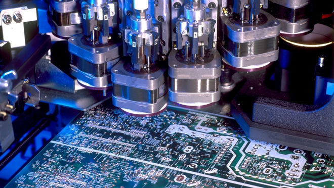
- SMT: Components are placed by automated pick-and-place machines, followed by reflow soldering ovens that melt solder paste and secure the parts to the board.
- Through-Hole: Components are often inserted manually or with the help of insertion machines, then soldered using wave soldering or by hand.
SMT’s reliance on automation allows for much faster production rates and lower labor costs, especially for large-scale manufacturing. Through-hole, while slower, offers advantages in prototyping and repair, as components are easier to replace or modify.
Key Differences in Design and Application
When considering the difference between SMT and through hole assembly, several factors stand out:
| Aspect | Surface Mount Technology | Through-Hole Assembly |
|---|---|---|
| Component Size | Very small, high-density | Larger, bulkier |
| Board Space | Efficient use, double-sided possible | Requires more space, single-sided preferred |
| Mechanical Strength | Lower, not ideal for stress | High, suitable for connectors and heavy parts |
| Assembly Speed | Fast, highly automated | Slower, often manual |
| Repair/Prototyping | Challenging, requires skill | Easy to modify and repair |
| Cost (High Volume) | Lower per unit | Higher per unit |
Choosing the Right Assembly Method
Selecting between SMT and through-hole assembly depends on several criteria:
- Product Size and Weight: For compact, lightweight devices, SMT is usually preferred.
- Mechanical Demands: If the product will face vibration or physical stress, through-hole is often better for connectors and large components.
- Production Volume: SMT is more cost-effective for mass production, while through-hole suits low-volume or custom builds.
- Prototyping and Testing: Through-hole is easier for quick changes and manual assembly during development.
Many modern PCBs use a hybrid approach, combining SMT for most components and through-hole for connectors or parts needing extra strength. For a step-by-step look at how electronics are built, the how electronics are manufactured article provides a helpful walkthrough.

Advantages and Limitations of Each Technique
Benefits of Surface Mount Technology
- Enables miniaturization and high-density circuits
- Faster, more automated assembly process
- Lower production costs for large runs
- Improved electrical performance due to shorter leads
Strengths of Through-Hole Assembly
- Superior mechanical strength for heavy or stressed components
- Better suited for prototyping and manual modifications
- Reliable for harsh environments and mission-critical applications
Limitations to Consider
- SMT can be difficult to repair or rework without specialized equipment
- Through-hole requires more board space and is slower to assemble
- Not all components are available in both formats, which may affect design choices
Further Learning and Resources
For those interested in a deeper dive into PCB assembly, the comprehensive PCB basics tutorial offers detailed explanations and visuals. Additionally, exploring electronics fabrication basics can provide more background on the manufacturing environment and processes.
Frequently Asked Questions
What is the main difference between SMT and through-hole assembly?
The core distinction lies in how components are mounted to the PCB. SMT places components directly onto the board’s surface, while through-hole involves inserting leads through drilled holes and soldering them on the opposite side.
When should I use through-hole assembly instead of SMT?
Through-hole is best for applications requiring high mechanical strength, such as connectors or components exposed to physical stress. It’s also preferred for prototyping and environments where reliability is critical.
Can both SMT and through-hole components be used on the same PCB?
Yes, many modern designs use a combination of both methods. This hybrid approach allows designers to optimize for size, cost, and mechanical requirements within a single board.