

Ensuring that electrical circuits are complete and free from faults is a fundamental step in electronics manufacturing and repair. Circuit continuity testing is a straightforward yet essential process used to verify the presence of a complete path for current flow. By confirming that connections are intact and components are properly linked, technicians can quickly identify open circuits, broken traces, or faulty solder joints. This guide provides a practical overview of how continuity checks work, the tools involved, and best practices for reliable results.
Understanding the basics of continuity checks is valuable not only for professional engineers but also for hobbyists and anyone involved in troubleshooting electronic devices. Before diving into the details, it’s helpful to learn about what are test points on a PCB, as these designated spots are often used during the testing process.

Understanding the Purpose of Continuity Checks
The main goal of a continuity test is to determine whether an electrical path exists between two points. If the path is unbroken, current can flow, and the circuit is said to have continuity. If there is a break—caused by a damaged wire, faulty component, or poor solder joint—the circuit is open, and current cannot pass through.
This process is vital in various stages of electronics development, from initial assembly to final inspection. It helps prevent issues that could lead to device malfunction, safety hazards, or costly rework. In manufacturing environments, continuity testing is often integrated into automated inspection systems to ensure every board meets quality standards before shipment.
Essential Tools for Circuit Continuity Testing
The most common instrument used for checking continuity is the digital multimeter. Most modern multimeters feature a dedicated continuity mode, which emits an audible beep when a low-resistance path is detected between the probes. This feature allows technicians to quickly verify connections without constantly watching the display.
- Digital Multimeter: Offers visual and audible feedback for continuity checks.
- Analog Multimeter: Uses a needle to indicate resistance; less common but still effective.
- Dedicated Continuity Tester: A simple device designed solely for this purpose, often with a light or buzzer.
When selecting a tool, consider the sensitivity, probe quality, and ease of use. For detailed manufacturing processes, such as those described in the ultimate guide to electronics manufacturing, advanced testers may be integrated into automated systems for rapid, high-volume inspection.
Step-by-Step Guide to Performing a Continuity Test
Conducting a continuity check is a straightforward process, but following the correct steps ensures accurate and safe results. Here’s a practical walkthrough:
- Power Off the Circuit: Always disconnect power before testing. Applying a continuity test to a live circuit can damage the tester or cause injury.
- Set the Multimeter: Turn the dial to the continuity setting, usually indicated by a sound wave or diode symbol.
- Test the Probes: Touch the two probes together. The meter should beep or show near-zero resistance, confirming the tester is working.
- Probe the Circuit: Place one probe at each end of the connection you want to test. A beep or low resistance reading indicates continuity; no beep or infinite resistance means the path is open.
- Interpret the Results: If continuity is confirmed, the connection is intact. If not, inspect for visible breaks, cold solder joints, or damaged components.
For more complex assemblies, such as printed circuit boards, it’s important to identify the correct test points and reference the schematic diagram. This ensures you are checking the intended connections and not overlooking parallel paths or hidden faults.
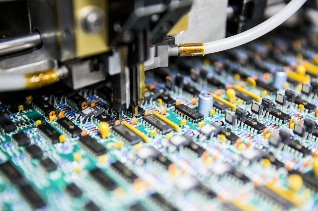
Common Applications in Electronics Manufacturing
Continuity checks are a routine part of quality assurance in electronics production. They are used to:
- Verify the integrity of PCB traces and vias
- Check for solder bridges or shorts between adjacent pads
- Ensure connectors and cables are properly assembled
- Validate repairs after component replacement
In high-volume manufacturing, automated systems may perform these tests at multiple stages. For example, after soldering components, machines can probe specific points to confirm that all intended connections are present and that no accidental shorts exist.

Troubleshooting Tips for Reliable Continuity Testing
Even with the right tools, achieving accurate results requires attention to detail. Here are some practical tips to avoid common pitfalls:
- Clean Probe Tips: Dirt or oxidation can prevent good contact. Wipe probes before testing.
- Avoid Parallel Paths: In complex circuits, multiple routes can create false positives. Isolate the path if possible.
- Check for Intermittent Faults: Gently flex wires or boards while testing to reveal hidden breaks.
- Consult the Schematic: Always reference the circuit diagram to ensure you’re testing the correct locations.
- Use Proper Test Points: Many PCBs include designated spots for probes. Learn more about their role in what are test points.
For advanced troubleshooting and inspection, additional methods such as those described in electronics inspection methods can complement continuity checks, especially when diagnosing complex faults.
Integrating Continuity Checks Into Quality Control
Incorporating continuity verification into the standard workflow helps catch defects early and ensures product reliability. In manufacturing, this often involves a combination of manual and automated testing. Operators may use handheld meters for spot checks, while automated test equipment can rapidly scan entire boards.
Documenting test results and establishing clear procedures also supports traceability and continuous improvement. For example, tracking the frequency and location of failures can highlight process weaknesses or design issues that need attention. Understanding related processes, such as the copper plating process explained, can further enhance quality control by ensuring robust connections throughout the board.
Frequently Asked Questions
What does a successful continuity test indicate?
A successful test confirms that there is a complete, low-resistance path between two points, meaning the circuit can conduct current as intended. This is a key indicator that connections are intact and the circuit is not open.
Can continuity testing detect all types of faults?
While continuity checks are excellent for finding open circuits and verifying connections, they do not detect all issues. For example, they may not reveal high-resistance joints, partial shorts, or component-level faults. Additional inspection methods may be needed for comprehensive diagnostics.
Is it safe to perform continuity checks on powered circuits?
No, you should always disconnect power before performing these tests. Applying a continuity tester to a live circuit can damage the instrument and pose a safety risk to the user.
How often should continuity checks be performed in manufacturing?
The frequency depends on the production process and quality requirements. Many manufacturers perform these tests after major assembly steps, during final inspection, and whenever repairs or modifications are made.
Conclusion
Mastering the process of verifying electrical paths is crucial for anyone involved in electronics assembly, repair, or quality assurance. By following best practices and using the right tools, you can quickly identify and resolve connectivity issues, ensuring reliable and safe operation of electronic devices. For further reading on related topics, explore resources on how vias are made in PCBs or learn about how stencil printing works in PCB assembly.