

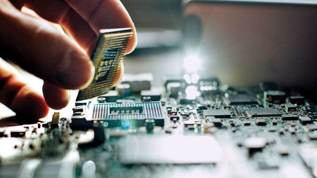
When electronic devices malfunction, the consequences can range from minor inconveniences to critical system failures. Understanding the root causes behind these issues is essential for manufacturers, engineers, and quality assurance teams. Electronics failure analysis is a systematic approach used to identify, diagnose, and prevent failures in electronic assemblies and components. This process not only helps in improving product reliability but also minimizes costly recalls and downtime.
In this article, we’ll walk through the core concepts, common causes, and step-by-step methodologies used in evaluating failed electronics. Whether you’re involved in design, manufacturing, or repair, gaining a solid grasp of these techniques can significantly enhance your troubleshooting capabilities and product outcomes.
For those interested in the finer details of circuit board testing, you may also want to explore what are test points and how they play a role in diagnostics.
What Is Electronics Failure Analysis?
At its core, electronics failure analysis is the practice of investigating why an electronic device or component has stopped working as intended. The goal is to determine the underlying mechanism of failure—be it electrical, mechanical, thermal, or chemical—and to use this knowledge to prevent similar issues in future designs or manufacturing runs.
This process often involves a combination of visual inspection, electrical testing, and advanced analytical techniques. The findings can reveal whether the failure was due to design flaws, material defects, manufacturing errors, or external stresses such as overvoltage or environmental exposure.
Common Causes of Electronic Component Failures
Understanding the typical reasons behind electronic malfunctions is a key step in effective troubleshooting. Some of the most frequent culprits include:
- Manufacturing defects: Issues such as poor solder joints, misaligned components, or contamination during assembly can lead to intermittent or permanent failures.
- Design errors: Inadequate circuit layout, insufficient thermal management, or improper component selection can cause premature breakdowns.
- Material degradation: Over time, materials like plastics, metals, and semiconductors can degrade due to heat, humidity, or chemical exposure.
- Electrical overstress (EOS): Surges, spikes, or static discharge can damage sensitive circuitry.
- Environmental factors: Vibration, shock, or exposure to corrosive substances can physically or chemically damage components.
Each of these failure modes requires a different investigative approach, making it important to tailor the analysis to the suspected cause.
Step-by-Step Process for Analyzing Electronic Failures
A structured methodology ensures that no detail is overlooked during the investigation. Here’s a typical sequence followed by professionals in the field:
- Initial Assessment: Gather background information such as device history, operating conditions, and failure symptoms. This helps narrow down possible causes.
- Visual Inspection: Use magnification tools to check for obvious signs of damage—burn marks, cracked components, or soldering issues.
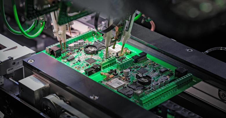
- Non-Destructive Testing: Techniques like X-ray imaging, acoustic microscopy, or thermal imaging can reveal hidden defects without damaging the sample.
- Electrical Testing: Measure voltages, currents, and resistances to identify abnormal readings. This step often involves using oscilloscopes, multimeters, or specialized test fixtures.
- Destructive Analysis: If non-destructive methods are inconclusive, the device may be physically sectioned for detailed examination using scanning electron microscopy (SEM) or energy-dispersive X-ray spectroscopy (EDS).
- Root Cause Identification: Correlate all findings to pinpoint the exact mechanism of failure.
- Reporting and Recommendations: Document the results and suggest corrective actions, whether it’s a design change, process improvement, or supplier adjustment.
For a deeper dive into inspection techniques, see our overview of electronics inspection methods.
Key Tools and Techniques Used in Failure Analysis
The effectiveness of any electronics failure analysis depends on the tools and methods employed. Some of the most widely used include:
- Optical Microscopes: Essential for spotting surface defects and soldering issues.
- X-ray Inspection: Reveals hidden problems such as internal cracks or voids in solder joints.
- Scanning Electron Microscopy (SEM): Provides high-resolution images of fractures, corrosion, or contamination at the microscopic level.
- Thermal Imaging: Detects hotspots that may indicate short circuits or excessive power dissipation.
- Electrical Test Equipment: Oscilloscopes, logic analyzers, and curve tracers help diagnose circuit behavior under various conditions.
The choice of technique depends on the suspected failure mode, the value of the device, and the need to preserve evidence for further analysis.
Benefits of Conducting Thorough Failure Investigations
Investing in comprehensive failure analysis offers several advantages:
- Improved reliability: Identifying and addressing root causes leads to more robust products.
- Reduced costs: Early detection of systemic issues can prevent large-scale recalls and warranty claims.
- Enhanced customer trust: Demonstrating a commitment to quality and continuous improvement builds brand reputation.
- Regulatory compliance: Many industries require detailed documentation of failure investigations for safety and liability purposes.
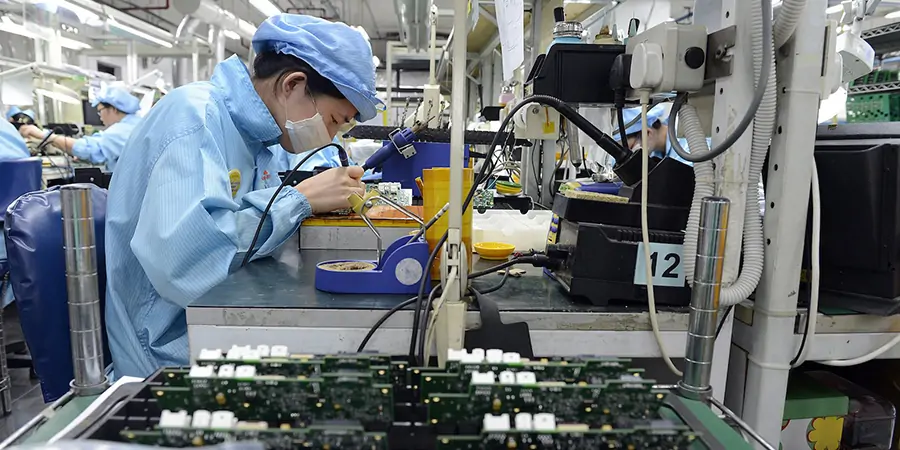
For an overview of how electronic products are manufactured and the role of quality control, see this guide to the electronics manufacturing process.
Integrating Failure Analysis Into the Product Lifecycle
Incorporating failure investigation throughout the design and manufacturing stages is crucial for long-term success. Here are some best practices:
- Perform design reviews and stress testing before mass production.
- Use statistical process control to monitor manufacturing consistency.
- Establish feedback loops between field returns, engineering, and suppliers.
- Document all findings and corrective actions for future reference.
Additionally, understanding related processes such as copper plating process explained and how vias are made in PCBs can help in pinpointing where failures may originate within the assembly workflow.
Frequently Asked Questions
What are the most common signs of failure in electronic assemblies?
Typical indicators include intermittent operation, complete loss of function, visible damage such as burnt or cracked components, and abnormal electrical readings. Early detection of these symptoms can help prevent further damage and simplify troubleshooting.
How does failure analysis differ from routine quality control?
While quality control focuses on preventing defects during production, failure analysis investigates the reasons behind a malfunction after it has occurred. The goal is to identify the root cause and implement corrective actions to avoid recurrence.
Can failure analysis help improve future product designs?
Absolutely. By understanding the mechanisms behind past failures, engineers can refine designs, select better materials, and adjust manufacturing processes to enhance reliability and performance in future products.
What role do test points play in diagnosing electronic failures?
Test points provide accessible locations on a circuit board for measuring voltages, signals, or currents. They are invaluable for isolating faults and verifying circuit behavior during both production testing and post-failure analysis.